Symbiosis of VHF and FMT
Colleagues, I would like to offer you an unusual use of a beacon on VHF frequencies, as a multifunctional device. Surely you have heard about the project FMT, which is launched as a competition among radio amateurs.
In this case, such a beacon is a useful tool, which provides the ability to calibrate various radio equipment. If the FMT project develops, such beacons in the future, will allow access to accurate signals, will allow a new quality level to approach the radio amateur community to the practical implementation of their new knowledge.
This can be expressed in the end of course in competitive sports component.
I will describe such a beacon, from my website, devoted to FMT.
In Ussuriisk – operating the beacon on the frequency 144.950 000 MHz. The transmitting power is 3 Watt.
QTH Locator: PN53xt
It emits a frequency-modulated signal with 100ms duration and 1PPS period. The pulse filling frequency is exactly 1000 Hz. One second edge of the generated radio impulse is referenced to the global UTC time.
Temporal deviation of such a radio impulse received by any analog VHF receiver is not more than 0.3ms, relatively to the global 1PPS.
Such a small value of errors is provided by using a special switch of audio frequency in the modulator of the transmitter.
Only once every three minutes a telegraphic identification signal – CQ FMT de RU0LL k sounds.
The task of these signals is to allow the local meters to be bound to a particularly accurate global 1PPS signal via VHF channel. This signal, for example, can be directly applied in the synchronization of measuring instruments in determining the distances to precise time stations on the VHF band.
The beacon signal can be used to calibrate various measuring equipment and research. For example, calibration of any frequency meter can be performed on such a VHF channel with great accuracy. Use the comparator mode, the mode of measuring frequency ratios on the two input channels of the frequency meter, one of which is 1PPS.
When using modern VHF receivers and radios, the inevitable delay resulting from the complex process of modulation-demodulation frequencies must be taken into account.
Radio stations with digital paths have a delay of many tens and hundreds of milliseconds, which casts doubt on their application in FMT tasks.
In any case, it is desirable to measure the radio individually and find out this delay. In the future, it can be taken into account as a correction for particularly accurate measurements.
Now let’s consider how the beacon is hardware implemented.
In numerous studies, a large number of types of radios were discarded according to different criteria. The choice was made in favor of the transmitter of Kenwood TK-768G radio.
This model was first of all pleased with its excellent frequency synthesizer, which allowed to get the accuracy of the output frequency formation better than one Hertz.
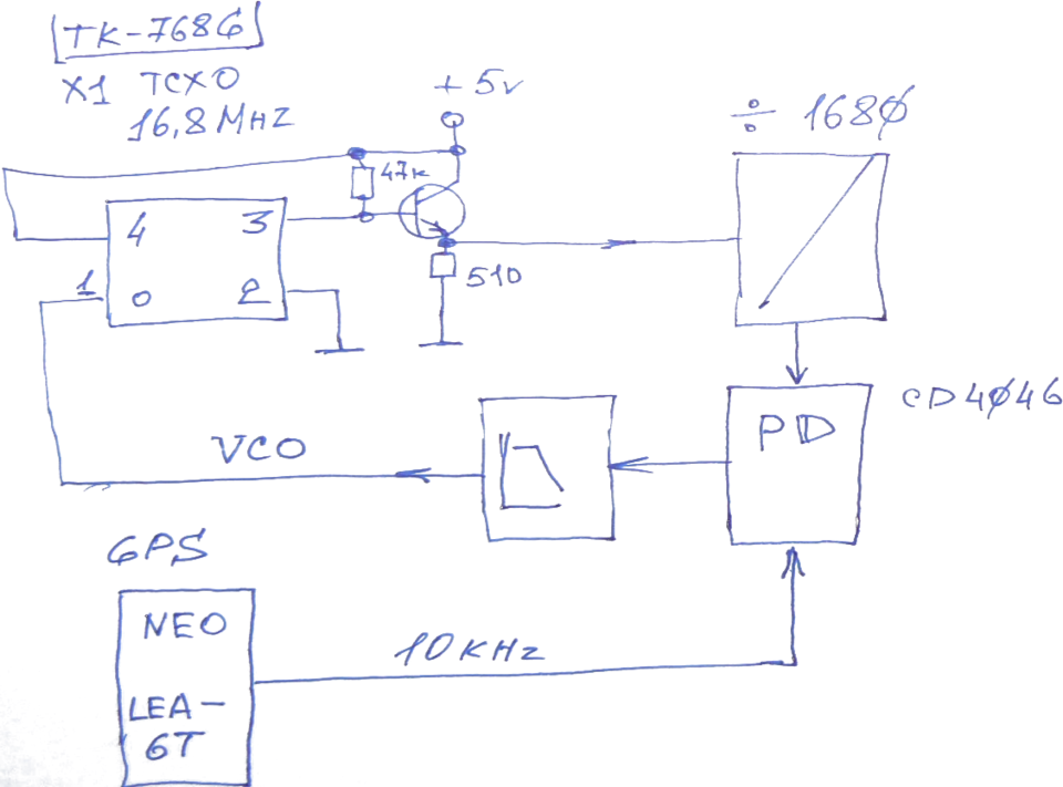
This accuracy was achieved by synchronizing the internal oscillator of the radio to the reference frequency signals received directly from the satellite navigation systems. An abbreviated block diagram can be seen below.
Draw by hand, sorry, but the original 🙂
The radio uses a 16.8 MHz X1 TCXO reference clock on board. By dividing the frequency by 1680, we get a frequency of 10KHz. Feed this signal to the phase detector PD. On the second input of PD we feed the 10KHz signal directly from the navigation receiver, which itself directly forms this precision frequency. Passing after the phase detector through a low frequency filter with a short integration time, we feed the VCO voltage directly to the radio reference oscillator.
Direct measurements of the radio output frequency resulted in values that meet the criteria of an FMT transmitting station. The frequency accuracy measured with a GPSDO-synchronized frequency meter C3-63 is 144,950,000 MHz.
See the beacon signal conditioning and modulation node of the transmitter.

A signal switching scheme based on the CD4066 switch was chosen. This method allowed to minimize the delays of signals passing through the keys to values much less than a microsecond.
There are four basic signals at the input of the modulator. 1PPS, 1000 Hz, beacon recognition signal in_CW_mod and PTT. The inclusion algorithm of the sequences is set by the microcontroller PIC 16F84, but which is not involved in the circuits of passage and formation of the main 1PPS signal.
And yet, the signal would have a delayed response measured on the receiving side, in total reaching about 470 µs relative to 1PPS.
This delay is caused by transients in the FM transmitter modulator itself, in the very beginning of the deviation formation.
In this measurement we used the Motorola 2550 service device as a reference receiver.
But such parasitic delay in the RU0LL beacon can be compensated by programming the GNSS receiver module itself, so that the formation of the basic 1 PPS UTC time signal would be 470 µs ahead of time. Thus we have at the output of the beacon transmitter a signal with a minimum deviation of 1PPS pulses not exceeding units of microseconds from the absolute value of UTC time.
This measurement was made with the HP 54100D, by the direct comparisons of the pulses at the VHF discriminator output and the original 1PPS pulse taken from the independent GNSS receiver.
Modernization of the transmitter reference oscillator.
The modifications were minimal. An emitter repeater and two coaxial cables are added. One takes 16.8MHz to the divider, the other supplies VCO correction voltage.
In the aluminum shield on top, two holes are drilled for the output of the coaxial cables. The shield cover is installed in place is mandatory.


The beacon transmitter modulator.
Microcontroller
Comparator
Commutator
Deviation level balancing circuit
PTT reset circuit.

FAHR CD4046 with integrator
Delimiter at 1680 (193IE2, 564IE15)
The 1000Hz frequency generation circuit (synchronous division method from main reference frequency).
Transformer power supply with linear stabilizers of the analog-digital beacon circuit.

Claim
I hope this information will be useful for researchers who are ready to practice and improve their radio engineering skills.
There are probably colleagues among readers who are interested in this direction, ready to get involved in the FMT project at their places.
I invite you to discuss this great direction, in a constructive way, in which VHF can take its important applied place, providing local consumers with useful and accurate signals.
73! Alex RU0LL
If you have found a spelling error, please, notify us by selecting that text and pressing Ctrl+Enter.